68.4A
total current draw
23
device(s)
Craig's Other Sling 4
Electrical Load Planning and VP-X Config
Aircraft Overview - Devices

The following devices represent your aircraft, and will be used to generate your personalized
electrical diagram,
VP-X pinout and electrical build
buying guide.
Instruments/Avionics
|
Garmin G3X Touch GDU 460/465
|
| pin name | actual current draw | circuit breaker value | min wire size |
VP-X pin | backup? | current fault detect? | switch | bank preference |
|---|
| Garmin GDU 460 |
2.0A |
5.0A | 20g |
J12-3 |
Method C |
No |
Avionics Master |
Bank A |
| notes: Left Monitor |
|
Garmin GSA 28
|
| GSA 28 - Pitch |
2.8A |
5.0A | 20g |
J8-4 |
none |
Yes |
Avionics Master |
Bank A |
| notes: Autopilot Servo |
|
Garmin Misc.
|
| Garmin Misc. |
1.2A |
5.0A | 20g |
J8-6 |
Method C |
Yes |
Avionics Master |
Bank B |
| notes: GEA 24 (EIS) .4A , GSU 25 (ADAHRS) .2A , GMC 307 AP (Ctl Pnl) .1A , GAD 29 (Data Con) .1A , GI 260 (AOA) .4A |
|
Garmin GDL 39R
|
| Garmin GDL 39R |
0.5A |
5.0A | 20g |
J8-1 |
none |
Yes |
Avionics Master |
Bank A |
| notes: ADS-B Receiver. Current is TBD |
|
Garmin GTR 20 Remote comm
|
| GTR 20 Remote |
7.5A |
8.0A | 18g |
J12-1 |
Method C |
Yes |
Avionics Master |
Bank A |
|
Garmin GTX 23 ES Xponder
|
| GTX 23 ES |
3.1A |
4.0A | 20g |
J8-3 |
none |
Yes |
Avionics Master |
Bank A |
|
Audio Panel
|
| Audio Panel |
3.5A |
5.0A | 20g |
J12-7 |
none |
No |
Avionics Master |
Bank A |
|
GRT Mini EFIS
|
| GRT Mini |
0.3A |
5.0A | 20g |
J8-7 |
none |
No |
Avionics Master |
Bank B |
|
Garmin GTN 650 (14v)
|
| 650 Nav |
2.2A |
8.0A | 18g |
J10-5 |
none |
No |
Avionics Master |
Bank A or B |
| 650 Comm |
0.5A |
10.0A | 18g |
J8-2 |
none |
No |
Avionics Master |
Bank A or B |
|
Garmin GSA 28
|
| GSA 28 - Roll |
2.8A |
5.0A | 20g |
J8-5 |
none |
Yes |
Avionics Master |
Bank A |
| notes: Autopilot Servo |
Lights
|
Landing light (100W)
|
| pin name | actual current draw | circuit breaker value | min wire size |
VP-X pin | backup? | current fault detect? | switch | bank preference |
|---|
| Left Landing lgt |
3.8A |
5.0A | 18g |
J12-8 |
none |
Yes |
Land Lt |
Bank A |
| notes: AeroLEDS Sunspot 36LX |
|
Taxi light
|
| Right Taxi lgt |
3.8A |
5.0A | 18g |
J10-7 |
none |
Yes |
Taxi Lt |
Bank B |
| notes: AeroLEDS Sunspot 36LX |
|
Nav lights (LED)
|
| Nav lights |
1.4A |
5.0A | 18g |
J10-10 |
none |
Yes |
Nav Lt |
Bank B |
| notes: (2) Aveo Ultra Aurora + (1) Aveo PosiStrobe XP |
|
Strobes
|
| Strobes |
9.2A |
10.0A | 18g |
J10-3 |
none |
Yes |
Strobe Lt |
Bank B |
| notes: (2) Aveo Ultra Aurora (wings) + (1) Aveo PosiStrobe XP (tail) |
|
Taxi light
|
| Left Taxi lgt |
3.8A |
5.0A | 18g |
J12-12 |
none |
Yes |
Taxi Lt |
Bank A |
| notes: AeroLEDS Sunspot 36LX |
|
Landing light (100W)
|
| Rt Landing lgt |
3.8A |
5.0A | 18g |
J10-6 |
none |
Yes |
Land Lt |
Bank B |
| notes: AeroLEDS Sunspot 36LX |
|
Eyeball lights (LED)
|
| Eyeball lights |
0.2A |
1.0A | 20g |
J1-2 |
none |
No |
Cabin Lt |
Bank A or B |
Accessories/Ignition/Other
|
Pitot heat 2
|
| pin name | actual current draw | circuit breaker value | min wire size |
VP-X pin | backup? | current fault detect? | switch | bank preference |
|---|
| Pitot heat 2 |
12.0A |
15.0A | 14g |
J12-2 |
none |
Yes |
Pitot Heat |
Bank A |
| notes: Garmin GAP-26 Heated Pitot |
|
Boost pump
|
| Boost pump |
1.5A |
5.0A | 20g |
J10-8 |
none |
Yes |
Boost Pump |
Bank B |
Electrical System
|
B&C Pri Alt
|
| pin name | actual current draw | circuit breaker value | min wire size |
VP-X pin | backup? | current fault detect? | switch | bank preference |
|---|
| Alternator Field |
2.5A |
5.0A | 20g |
J12-11 |
none |
No |
Alternator |
Bank A |
| Alternator Vsense |
0.1A |
2.0A | 20g |
J1-1 |
none |
No |
always on |
Bank A |
|
SD-20 BU Alt
|
| Alt - BU - Field |
2.5A |
5.0A | 20g |
J10-2 |
none |
No |
BU Alternator |
Bank B |
| Alt - BU - Vsense |
0.1A |
2.0A | 20g |
J10-4 |
none |
No |
always off |
Bank B |
VP-X Pinout and Configuration
Currently configuring
VP-X Pro, 14 volt.
All device pins assigned!
J8 |
| | pin |
bank |
VP-X pin name |
power pin name | current draw |
wire size | circuit breaker | switch |
current fault detect |
|
|---|
| |
1 |
A |
5A-1 output |
Garmin GDL 39R
|
0.5
|
20
|
5.0
|
Avionics Master
|
Yes
|
|
| power pin notes: ADS-B Receiver. Current is TBD |
| |
2 |
A |
10A-1 output |
650 Comm
|
0.5
|
18
|
10.0
|
Avionics Master
|
No
|
|
| |
3 |
A |
5A-2 output |
GTX 23 ES
|
3.1
|
20
|
4.0
|
Avionics Master
|
Yes
|
|
| |
4 |
A |
5A-3 output |
GSA 28 - Pitch
|
2.8
|
20
|
5.0
|
Avionics Master
|
Yes
|
|
| power pin notes: Autopilot Servo |
| |
5 |
A |
5A-4 output |
GSA 28 - Roll
|
2.8
|
20
|
5.0
|
Avionics Master
|
Yes
|
|
| power pin notes: Autopilot Servo |
| |
6 |
B |
5A-5 output |
Garmin Misc.
|
1.2
|
20
|
5.0
|
Avionics Master
|
Yes
|
|
| power pin notes: GEA 24 (EIS) .4A , GSU 25 (ADAHRS) .2A , GMC 307 AP (Ctl Pnl) .1A , GAD 29 (Data Con) .1A , GI 260 (AOA) .4A |
| |
7 |
B |
5A-6 output |
GRT Mini
|
0.3
|
20
|
5.0
|
Avionics Master
|
No
|
|
| |
8 |
B |
5A-7 output |
not assigned
|
|
|
|
|
|
|
J10 |
| | pin |
bank |
VP-X pin name |
power pin name | current draw |
wire size | circuit breaker | switch |
current fault detect |
|
|---|
| |
1 |
A|B |
Starter Switch |
|
|
|
|
|
|
|
| |
2 |
B |
5A-8 output |
Alt - BU - Field
|
2.5
|
20
|
5.0
|
BU Alternator
|
No
|
|
| |
3 |
B |
10A-2 output |
Strobes
|
9.2
|
18
|
10.0
|
Strobe Lt
|
Yes
|
|
| power pin notes: (2) Aveo Ultra Aurora (wings) + (1) Aveo PosiStrobe XP (tail) |
| |
4 |
B |
5A-9 output |
Alt - BU - Vsense
|
0.1
|
20
|
2.0
|
always off
|
No
|
|
| |
5 |
B |
10A-3 output |
650 Nav
|
2.2
|
18
|
8.0
|
Avionics Master
|
No
|
|
| |
6 |
B |
15A-1 output |
Rt Landing lgt
|
3.8
|
18
|
5.0
|
Land Lt
|
Yes
|
|
| power pin notes: AeroLEDS Sunspot 36LX |
| |
7 |
B |
5A-10 output |
Right Taxi lgt
|
3.8
|
18
|
5.0
|
Taxi Lt
|
Yes
|
|
| power pin notes: AeroLEDS Sunspot 36LX |
| |
8 |
B |
5A-11 output |
Boost pump
|
1.5
|
20
|
5.0
|
Boost Pump
|
Yes
|
|
| |
9 |
|
To GND block |
|
|
|
|
|
|
|
| |
10 |
B |
5A-12 output |
Nav lights
|
1.4
|
18
|
5.0
|
Nav Lt
|
Yes
|
|
| power pin notes: (2) Aveo Ultra Aurora + (1) Aveo PosiStrobe XP |
J12 |
| | pin |
bank |
VP-X pin name |
power pin name | current draw |
wire size | circuit breaker | switch |
current fault detect |
|
|---|
| |
1 |
A |
10A-4 output |
GTR 20 Remote
|
7.5
|
18
|
8.0
|
Avionics Master
|
Yes
|
|
| |
2 |
A |
15A-2 output |
Pitot heat 2
|
12.0
|
14
|
15.0
|
Pitot Heat
|
Yes
|
|
| power pin notes: Garmin GAP-26 Heated Pitot |
| |
3 |
A |
10A-5 output |
Garmin GDU 460
|
2.0
|
20
|
5.0
|
Avionics Master
|
No
|
|
| power pin notes: Left Monitor |
| |
4 |
|
To GND block |
|
|
|
|
|
|
|
| |
5 |
B |
Flap motor |
enabled
|
|
|
5
|
|
|
|
| |
6 |
B |
Flap motor |
enabled
|
|
|
|
|
|
|
| |
7 |
A |
10A-6 output |
Audio Panel
|
3.5
|
20
|
5.0
|
Avionics Master
|
No
|
|
| |
8 |
A |
5A-13 output |
Left Landing lgt
|
3.8
|
18
|
5.0
|
Land Lt
|
Yes
|
|
| power pin notes: AeroLEDS Sunspot 36LX |
| |
9 |
A |
EFIS power output |
| |
10 |
A |
3A-1 output |
not assigned
|
|
|
|
|
|
|
| |
11 |
A |
Alternator Field |
Alternator Field
|
2.5
|
20
|
5.0
|
Alternator
|
|
|
| |
12 |
A |
15A-3 output |
Left Taxi lgt
|
3.8
|
18
|
5.0
|
Taxi Lt
|
Yes
|
|
| power pin notes: AeroLEDS Sunspot 36LX |
J1 |
| | pin |
bank |
VP-X pin name |
power pin name | current draw |
wire size | circuit breaker | switch |
current fault detect |
|
|---|
| |
1 |
A |
2A-1 output |
Alternator Vsense
|
0.1
|
20
|
2.0
|
always on
|
No
|
|
| |
2 |
A |
2A-2 output |
Eyeball lights
|
0.2
|
20
|
1.0
|
Cabin Lt
|
No
|
|
| |
3 |
|
Roll Trim: +2.5v |
disabled
|
|
|
|
|
|
|
| |
4 |
|
Roll Trim: gnd |
disabled
|
|
|
|
|
|
|
| |
5 |
|
Roll Trim: pos input |
disabled
|
|
|
|
|
|
|
| |
6 |
A |
Roll Trim: motor power |
disabled
|
|
|
|
|
|
|
| |
7 |
A |
Roll Trim: motor power |
disabled
|
|
|
|
|
|
|
| |
8 |
|
Pitch Trim: +2.5v |
enabled
|
|
|
|
|
|
|
| |
9 |
|
Pitch Trim: gnd |
enabled
|
|
|
|
|
|
|
| |
10 |
|
Pitch Trim: pos input |
enabled
|
|
|
|
|
|
|
| |
11 |
A/B |
Pitch Trim: motor pwr |
enabled
|
|
|
|
|
|
|
| |
12 |
A/B |
Pitch Trim: motor pwr |
enabled
|
|
|
|
|
|
|
| |
17 |
|
Flap pos input |
enabled
|
|
|
|
|
|
|
| |
18 |
|
Flap pos gnd |
enabled
|
|
|
|
|
|
|
| |
19 |
|
Flap pos +2.5v |
enabled
|
|
|
|
|
|
|
| |
20 |
|
Serial TX |
|
|
|
|
|
|
|
| |
21 |
|
Serial GND |
|
|
|
|
|
|
|
| |
22 |
|
Serial RX |
|
|
|
|
|
|
|
J2 |
| | pin |
bank |
VP-X pin name |
power pin name | current draw |
wire size | circuit breaker | switch |
current fault detect |
|
|---|
| |
1 |
|
External Switch Input 1 |
Alternator
|
|
|
|
|
|
|
| |
2 |
|
External Switch Input 2 |
BU Alternator
|
|
|
|
|
|
|
| |
3 |
|
External Switch Input 3 |
Avionics Master
|
|
|
|
|
|
|
| |
4 |
|
External Switch Input 4 |
Boost Pump
|
|
|
|
|
|
|
| |
5 |
|
External Switch Input 5 |
Land Lt
|
|
|
|
|
|
|
| |
6 |
|
External Switch Input 6 |
Taxi Lt
|
|
|
|
|
|
|
| |
7 |
|
External Switch Input 7 |
Nav Lt
|
|
|
|
|
|
|
| |
8 |
|
External Switch Input 8 |
Strobe Lt
|
|
|
|
|
|
|
| |
9 |
|
External Switch Input 9 |
Pitot Heat
|
|
|
|
|
|
|
| |
10 |
|
External Switch Input 10 |
Cabin Lt
|
|
|
|
|
|
|
| |
11 |
|
Starter annunciator input |
enabled
|
|
|
|
|
|
|
| |
12 |
|
Aux battery voltage input |
disabled
|
|
|
|
|
|
|
| |
14 |
|
Flap Up switch input |
enabled
|
|
|
|
|
|
|
| |
15 |
|
Flap Down switch input |
enabled
|
|
|
|
|
|
|
| |
16 |
|
Roll Left switch input |
disabled
|
|
|
|
|
|
|
| |
17 |
|
Roll Right switch input |
disabled
|
|
|
|
|
|
|
| |
18 |
|
Pitch Up switch Input |
enabled
|
|
|
|
|
|
|
| |
19 |
|
Pitch Dn switch Input |
enabled
|
|
|
|
|
|
|
The following device pins also have backup circuits (not show in above diagram):
| pin name | backup method | circuit breaker |
|---|
| GTR 20 Remote |
Method C |
8.0A |
| Garmin GDU 460 |
Method C |
5.0A |
| Garmin Misc. |
Method C |
5.0A |
Each column is explained below:
- Pin: the actual pin number on the connector.
- Bank: The VP-X Pro has two independent systems in one box. Each system is referred to as a "bank" of circuits. This column shows which bank that specific power pin is on. See Installation manual for details on determining which device goes on which bank.
- VP-X Pin Name: Describes the function of that pin. 5A-1 for example is a 5 amp circuit and it is the first five amp circuit. 10A-3 is a 10 amp circuit and is the third 10 amp circuit.
- Power pin name: You can give each pin a name that shows on the EFIS display.
- Current draw: The actual current drawn by a device. It is recommended you measure the ACTUAL current draw of each device prior to installation in the aircraft using an ammeter (commonly available from a friend at no cost or from Radio Shack, Sears, and electronic supply stores for a reasonable one).
- Wire size: the wire size you have specified to go between the VP-X and the device being powered.
- Circuit Breaker: The maximum current allowed for that pin. You can enter any value between 1 and the limit of that pin in increments of 1A. This value is equivalent to a circuit breaker or fuse. If a load draws more than the Circuit Breaker value, that circuit will fault. If too large of a breaker value is used, then the wire may overheat or fail. If too small a value is used, then the device may fault the circuit because it draws too much current.
- Switch: The number of the switch input (switch input 1 through 10) you have specified to control this pin. Or it can be set to 'always on' or 'always off'. Each switch input is labeled 1 through 10. You can assign multiple devices to a single switch, and conversely, a switch can control multiple devices. If you set the circuit to 'always on', it will be on anytime the VP-X is powered (i.e. the master switch is on). Multiple pins can be assignedto a single switch. You don't have to use all of the switch inputs.
- Current Fault detect: The pin can be configured to detect a "current fault" or open circuit. When a circuit with this feature enabled is turned on and does not draw any current for 3 seconds, the circuit is faulted. You can use this to detect burned out lights, faulty boost pump, failed avionics fan, or inop heated pitot tube for example. The minimum detectable current is about 100ma, so this should be used on devices like lights, strobes and loads that draw at least 100ma of current.
VP-X Switches
The VP-X allows up to 10 switches, configured to operate any number of connected devices. The following names are suggestions, you can
edit this list as required.
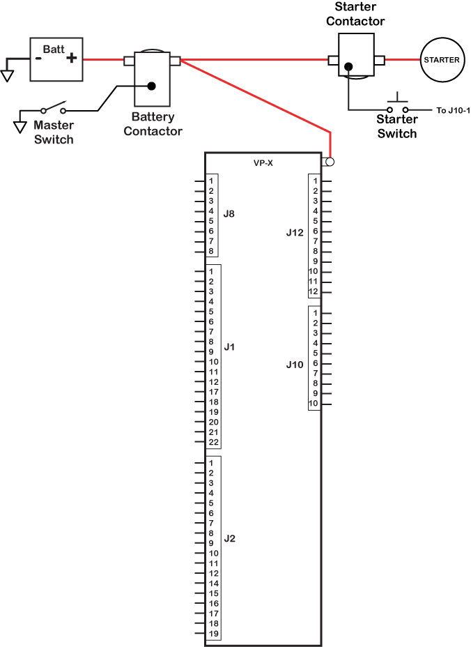
The trim and flap switches are wired to their own dedicated pins. The master switch is wired separately from the VP-X and directly to the master contactor. The Starter switch is wired in between the VP-X and the starter contactor.
Do not include trim, flap, master, or starter switches in the items below. Please see the
VP-X Installation Guide for details.
- Your Switches
-
-
1:
Alternator
-
2:
BU Alternator
-
3:
Avionics Master
-
4:
Boost Pump
-
5:
Land Lt
-
6:
Taxi Lt
-
7:
Nav Lt
-
8:
Strobe Lt
-
9:
Pitot Heat
-
10:
Cabin Lt
Device pins can also be assigned to "always on" or "always off" as required.


Garmin GDL 39R (5.0A CB, 20awg)
650 Comm (10.0A CB, 18awg)
GTX 23 ES (4.0A CB, 20awg)
GSA 28 - Pitch (5.0A CB, 20awg)
GSA 28 - Roll (5.0A CB, 20awg)
Garmin Misc. (5.0A CB, 20awg)
GRT Mini (5.0A CB, 20awg)
not used
Starter Switch
Alt - BU - Field (5.0A CB, 20awg)
Strobes (10.0A CB, 18awg)
Alt - BU - Vsense (2.0A CB, 20awg)
650 Nav (8.0A CB, 18awg)
Rt Landing lgt (5.0A CB, 18awg)
Right Taxi lgt (5.0A CB, 18awg)
Boost pump (5.0A CB, 20awg)
To GND block
Nav lights (5.0A CB, 18awg)
GTR 20 Remote (8.0A CB, 18awg)
Pitot heat 2 (15.0A CB, 14awg)
Garmin GDU 460 (5.0A CB, 20awg)
To GND block
Flap motor
Flap motor
Audio Panel (5.0A CB, 20awg)
Left Landing lgt (5.0A CB, 18awg)
EFIS power output
not used
Alternator Field (5.0A CB, 20awg)
Left Taxi lgt (5.0A CB, 18awg)
Alternator Vsense (2.0A CB, 20awg)
Eyeball lights (1.0A CB, 20awg)
not used
not used
not used
not used
not used
Pitch Trim: +2.5v
Pitch Trim: gnd
Pitch Trim: pos input
Pitch Trim: motor pwr
Pitch Trim: motor pwr
Flap pos input
Flap pos gnd
Flap pos +2.5v
Serial TX
Serial GND
Serial RX
Starter annunciator input
not used
Flap Up switch input
Flap Down switch input
not used
not used
Pitch Up switch Input
Pitch Dn switch Input
Alternator (switch)
BU Alternator (switch)
Avionics Master (switch)
Boost Pump (switch)
Land Lt (switch)
Taxi Lt (switch)
Nav Lt (switch)
Strobe Lt (switch)
Pitot Heat (switch)
Cabin Lt (switch)
The following device pins also have backup circuits (not show in above diagram):
| pin name | backup method | circuit breaker |
|---|
| GTR 20 Remote |
Method C |
8.0A |
| Garmin GDU 460 |
Method C |
5.0A |
| Garmin Misc. |
Method C |
5.0A |

Buying Guide
Some suggestion to help you source your electrical system.
Vertical Power
VP-X Pro
VP-X Pro Wiring Harness
EFIS Manufacturers
Avionics Dealers and Panel Builders
Electrical Supplies
Alternators
Builder Education Resources
Wiring Checklist
Review the following list to be sure you've included everything in your electrical
system planning:
- Alternator field
- Backup alternator field
- Starter
- Pitch trim
- Roll trim
- Yaw trim
- Flaps
- EFIS
- Backup EFIS
- Backup battery for EFIS
- Radios/Nav/GPS
- Audio panel/intercom
- Transponder
- Autopilot
- Avionics fan
- Defrost fan
- CO Detector
- XM Weather receiver
- AOA or stall warning
- Manifold pressure sensor
- Engine monitor
- Cabin lights
- Panel lights
- Seat heaters
- Landing light(s)
- Taxi light(s)
- Strobe lights
- Nav lights
- Fuel boost pump
- Electronic ignition
- Hobbs meter
- Music player, DVD, etc.
- Smoke system
- Power outlets
- Headset power
- Microswitches for doors, canopy, etc.